The Building Blocks
In the early days of computing, two foundational models emerged: Aiken’s Harvard architecture (1944) and von Neumann’s architecture (1945). Over time, engineers refined and extended both ideas, and the machines we use today blend elements of each. Modern CPUs expose a unified memory model like von Neumann envisioned, yet internally they borrow Harvard’s separation of instruction and data pathways to boost speed and parallelism. The result is a hybrid design that traces its lineage directly back to those two original approaches. There are ample resources explaining basic computer organization, so it won’t be covered here.
The focus here is the implementation stack. What is this? Figure 1 shows a hierarchy of five implementation layers. Each layer provides the primitives needed to construct the next. In this case the “top” is the most fundamental element that all lower layers depend on. The coverage is more about the building blocks (or nuts and bolts) and less about the architect's floorplans. Decoupling the two allows an architectural model to endure across vastly different hardware designs, with software only entering the hierarchy at layer 5.

Fig 1, A computer implementation stack
Although this site focuses on relay-based computing, the following discussion examines three logic-switch technologies fundamental to computer operation: relays, vacuum tubes, and transistors. Each independently played an important role in the history of computing. Understanding these 3 switching devices in relation to each other provides a wider perspective than just how relays were used. The Figure 1 model is deliberately kept simple. Let’s examine each layer.
The Stack
Layer 1: The Switch
Nothing computes or decides without the active (powered) on/off binary switch. This is not a hand operated switch. Rather it’s a 3-port device with a control port(s) that opens and closes a switch(s). Figure 2 shows the concept diagram of this type of switch. For this example, the circuit performs an inverter action, a HIGH In closes the switch and produces a LOW out (0V). When the input is LOW (0V) the switch opens and the Output is HIGH (+V). The control port is typically low current, and this causes switching action of a higher current/voltage if needed. There are many ways to wire switches and Fig 2 is just one example. The Rload resistor limits the current when the switch is on and other variations may not have this resistor.

Fig. 2. Conceptual electrically controlled switch
Figure 3 shows the Relay, Vacuum tube, and Transistor. Each can be modeled as a binary switch by the Figure 2 concept diagram. These three are the most important electrically controlled switching devices ever invented. Importantly, all three in this figure were manufactured by Western Electric with the designs by Bell Laboratories (both AT&T). There are more exotic experimental switches, but our focus is on the three well established types in Fig 3. See Appendix A.

Fig 3, Three primary switching devices from Western Electric
U650 Relay (1920s-50s), 300B Tube (1938), 2N67 Transistor (1953)
With 60 years of global dominance, Bell Labs was the premiere industrial research house worldwide from 1925 to ~1985. That’s an extraordinary run — no other industrial research lab has maintained world leadership for anything close to six decades. Lab scientists were awarded ten Nobel Prizes in physics and chemistry.
First, they defined the state of the art for relay design (telephone exchanges) for ~50 years. Siemens (Germany), Erickson (Sweden) and Automatic Electric Company (US) were also major relay innovators. They did not invent the relay; that was done in 1838 by Edward Davy (England). The Labs invented or co‑invented major tube families. Most famously, Bell Labs scientists invented the transistor in 1948. Telephone systems have a need for route switching and voice amplification, hence Bell Lab’s concentrated innovation efforts in these areas. Each switching-type generation improved important metrics – speed, size, power, cost, other.
Check out the History of the Relay for a deeper dive. Besides on/off switching, tubes and transistors can also linearly amplify analog signals with proper circuit design. Relays can’t linearly amplify analog signals. Interestingly, in 2026 Western Electric (new owners) still handmake vacuum tubes (model 300B) for high-end audio amplifiers.
Layer 2: Primitive Gates
If you are unfamiliar with logic gates it will help to review this explainer first (with an interactive explorer).
The most fundamental elements are the 6 logic gate types at layer 2 in Fig 1. The NAND and NOR gates are Negated AND & Negated OR, respectively. Inversion (also called negation) turns 0 to 1 and 1 to 0. All digital operations can be performed using only these primitives or clever logically equivalent circuits. Each of these gates are implemented using switches.
Figure 4 shows three example gates with supply (+V) voltage values of +12V, +350V, and +6V, respectively. Why are they so different? The supply voltages are selected based on the individual circuit design needs. Important for us, regardless of the actual voltage, a logic HIGH output is +V and a logic LOW output is at ground potential, zero volts.

Fig 4, relay, tube and transistor logic circuit examples
For the relay AND gate, if A and B are HIGH their respective relays engage and the output is HIGH (+12V in this case), else LOW. Without describing how resistors, tubes or transistors work (see Appendix A), the following gives a high-level explanation for how, for example, NOR and OR logic gates operate.
For the tube based NOR, when A and B are LOW (A = 0, B = 0), neither tube conducts electricity. Because no current flows through the pull-up resistor the output voltage stays at +350V, which represents a HIGH (1) state. If A or B = 1 then the output is LOW (0V) because one or both tubes are conducting.
For the transistor OR circuit, if either input is HIGH (respective transistor conducts) the output is HIGH (~6V). There are many variations of these circuits for each gate type.
Importantly, using only a voltage source, switches, wires and passive resistors all logic gate types can be built. Some modern designs use semiconductor diodes to assist. The AND gate and OR gate can be built using only diodes and resistors (DRL gates) and a switch is not strictly needed. This design approach has limits due to signal loss but it was used in some early designs. The IBM 608 (1957), an all-transistorized computer, used diode-resistor logic for AND/OR gating, with transistors only for inversion and level restoration. In contrast, the Colossus Mark 1 (England) [3] used about 1,500 vacuum tubes and no relays.
Layer 3: Combinational Logic Circuits
With gates available as building blocks, we can construct complex logic circuits. Figure 5 is an example of a “multiplexer” (Mux: k-in, 1-out), a commonly used module for digital designers. There are 4 data inputs and 2 selector inputs. The idea is for the 2 selector values to route one of the 4 inputs to the single output, Y. This is a chooser circuit and found often in computer design. See the Truth Table to see all four routing combinations. For example, S1 S0 = 1 1 routes only I3 to the output.
Notice it uses 3 primitive gates – AND, OR and the Inverter. No matter how complex, all digital circuits can be made from the primitive gates. There are clever circuit shortcuts for some designs but in the end, all circuits use the primitives in one way or another. It’s easy to imagine this circuit being packaged with 4+2 inputs, 1 output and 2 pins for power. There are 500+ different transistor-based modules available today. Search for the 74LS153 Mux module as an example. These are like Lego blocks for DIY computer builders. There are relay and tube equivalent Mux implementations, but they are not described here.

Fig 5, Building a multiplexer using gate primitives
Another important element is bit memory. Fig 6 shows a latching relay circuit. In a computer, memory is needed for both program and raw data storage. In the figure, there is a push button to engage the relay (it stays on once its contact closes) and a reset button to disengage it. There may be other contacts if needed. Using a relay to store bits is expensive! 1,000 bits need 1,000 relays. So, engineers looked for more efficient ways to store bits.
The first relay-based calculator from Bell Labs used 100-point crossbar switches to store ten decimal digits per switch. See examples here on a companion site dedicated to relay-based telephone systems. Also, some early relay (mostly) computers use short term “1-bit capacitor memory”, some used special mechanically latched relays, and some modern versions use semiconductor memory (often NAND based).

Fig 6, Relay latch circuit for 1 bit
Layer 4: Hardware Based Math
One of the most powerful logic modules is the 1-bit full adder. Experiment with an interactive single 1-bit adder here. Cascading cells enables composite adders of any length in hardware (4, 8, 16, 32 bits,…). See Fig 7 for a hardware 4-bit adder example. A and B each are 4 input bits, S (Sum) are the 4 output bits. Note that the Carry_out bit of each adder is connected to the Carry_in bit of the next adder in the chain. The final Carry_out bit may be forwarded to another adder chain to increase the effective adder bit length beyond 4 bits. Search for the transistorized 74LS83 4-bit adder module to learn more.
The R30 cascades six, 1-bit, relay-based full adders, resulting in a 6-bit adder. Each 1-bit adder needs only two relays. The adder is described elsewhere TBD on this site. Th R30's six-bit adder is cascaded (in 6 passes), via the microcontroller, to make a full 36-bit adder and used for all math operations.

Fig 7, Hardware 4-bit integer adder made of four small 1-bit adders
What about hardware multipliers and dividers? These are also made of one or more n-bit adders but with additional control logic to implement the methods that we all learned in primary school. Here is the systematic method for unsigned integer multiplication:
-
Bit Check: Look at the multiplier one bit at a time, from right to left.
-
Add if 1, skip if 0: If the bit is a 1, add the multiplicand into a running total (the accumulator). If it is a 0, add nothing.
-
Shift: Slide the multiplicand one bit left, set the new LSB with a zero, and move to the next bit.
-
Repeat: A simple controller repeats this cycle until every bit is checked and the final total is ready
With an effort to manage the multiplier and multiplicand exponents (adding exponents is equivalent to multiplying), this method can be extended to signed floating point numbers.
The R30 uses the methods above to multiply and the non-restoring method to divide. The R30 supports 32b floating point math with a dynamic range of (+-) 1.4×E-38 to 3.4E+38 based on its 36-bit adder discussed above. Its math accuracy conforms to IEEE 754 Standard for Floating-Point Arithmetic. See the explainer on relay adders here TBD.
Many vendors make Floating Point Math accelerators. These are digital chips that can “bolt on” to CPU hardware chips to improve calculation speeds (not expanded on here). Note too that there are many methods available to speed up hardware calcs (i.e. Booth’s algorithm for multiply) but these are beyond our coverage although the R30 uses Booth.
Layer 5: The Execution Layer
Layers 1 through 4 provide the nuts and bolts —switches, gates, decoders, adders, registers, storage and more. But none of these components can decide what to do on their own. Layer 5 provides the conductor: the control unit, instruction decoding logic, and sequencing hardware (all based on logic gates) that orchestrate data movement across the machine.
Of course, these four layers appear as “black boxes” to Layer 5 execution. So, it’s possible to design a hybrid computer using combos of the switches in Fig 2. For example, the IBM SSEC (Selective Sequence Electronic Calculator, 1948) is one of the largest switch hybrids ever built. It combined 12,500 vacuum tubes (for the arithmetic unit and high-speed control) with 21,400 electromechanical relays used for intermediate memory registers and sequence control [1]. There are no known hybrids that use all three switch types.
Another example is the famous ABC “first vacuum tube” computer (1939-42). It was more a calculator than a computer. Nonetheless it used tubes for all math and relays for program execution. See Endnote A.
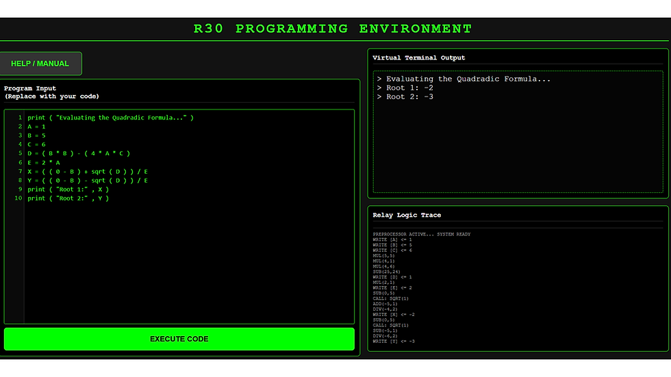
Fig 8, R30 program and output listings for solving a quadratic equation
Execution centers on the classic instruction cycle: Fetch, Decode, and Execute. A program counter (PC) holds the address of the next command, pointing to a location in memory (whether film, paper tape, electromagnetic store, or modern semiconductor memory). During the fetch phase, this instruction is loaded into an Instruction Register. Next, decoding logic inspects the bit pattern (the opcode).
Rather than running math directly, the decoder is essentially a traffic director: it asserts specific control lines that open multiplexers, enable register output onto shared buses, and tell the Layer 4 math units whether to add, invert, or shift. For the famous Zuse Z3 relay computer, about 25% of all the relays (plus some electromechanical stepping switches) were used for program execution. See Endnote B.
Layer 5 also manages the boundary between the internal machine state and the outside world via Input/Output (I/O). Using a microcontroller to manage all user I/O (WiFi connected tablet interface for the R30) is very practical and saves many relays. See Figure 8 for a R30 program listing and outputs for computing the two roots of the quadratic equation x*x + 5x + 6 = 0.
Appendix A
Tubes and Transistors
The Vacuum Tube
There are many excellent web resources on the operations of the vacuum tube and the transistor. This Appendix gives a tip-of -the-iceberg view of these important devices, especially functioning as binary switches.
In 1904, John Ambrose Fleming (British) patented the first vacuum tube diode, called the Fleming Valve. He realized that the Edison effect — one‑way electron flow inside a heated vacuum bulb — could be used as a radio-wave detector (passes one signal polarity, blocks the other). Edison himself had not recognized any practical use for it.
Fleming’s diode became the first practical electronic component, enabling reliable detection of wireless signals and effectively starting the electronics industry. In the figure below, if the "plate" element on the right side of the tube is positive in charge, it attracts the electrons from the heated filament. If the plate has a negative voltage the plate repels electrons. A vacuum provides a collision‑free path, allowing electrons to reach the plate more effectively. Fleming's invention is not a full on/off switch but very close to it.

The Fleming Valve Vacuum Tube
Lee de Forest’s invention — the Audion (1906) — was directly built on Fleming’s valve. De Forest began experimenting with the Edison effect and Fleming’s diode, trying to improve radio detection. He added a third electrode, the grid, creating the first triode (3 element) tube. The Audion became the foundation of radio broadcasting, long‑distance telephony, and eventually early computers.
Adding a grid (the control element in Figure 2 above) to the tube allowed it to function as an on/off binary switch or linear amplifier depending on how the tube was wired into the circuit. The grid (see image below) controls the flow of electrons from the cathode to the plate, allowing amplification, switching, and modulation. Without the grid, a tube is just a diode -- a Fleming Valve. By applying varying voltages to the grid element the electron flow is modulated as needed from binary on/off to varying in a linear fashion and causing amplification of audio and radio signals. Finally a new on/off electrical switch that is much faster than a relay!

The Lee de Forest Triode Vacuum Tube
Source: hamradioschool.com
AT&T (through Western Electric and what later became Bell Labs) bought the rights to De Forest’s Audion, and this purchase is what allowed them to industrialize and radically improve the triode. AT&T saw the potential for long‑distance telephone amplifiers and negotiated rights to use and develop the Audion. Over time the triode was used as a binary switch but this was not AT&T's original use case.
The first telephone call from New York to San Francisco in 1915 used three vacuum‑tube repeaters along the 3,400 mile (copper wire length) route. Surprisingly, before the tube AT&T used mechanical amplifiers (repeaters) for weak telephone
signals. Hundreds of model 6C8G "dual triode" (RCA or Sylvania likely) tubes were used in the original ABC tube computer (1942).
The Transistor
The transistor was invented (there were two versions) in late 1947-8 at Bell Telephone Laboratories by John Bardeen, Walter Brattain, and William Shockley. Their breakthroughs created the first solid-state device capable of amplifying and switching electrical signals. Several names were proposed and one was semiconductor triode [2], a nod to the triode tube. In the end, "transfer resistor" or transistor was chosen.
One way to understand a transistor is to picture a water faucet and its valve. Instead of water, electricity flows through it. Turning the handle is equivalent to applying a tiny trickle of electricity to the B (base) terminal causing electricity to flow between the C and E terminals. There is a similarity between the tube and transistor, each have 3 terminals and one controls the flow of current between the other two.
-
Tube: cathode → grid → plate
-
Transistor: emitter → base → collector
-
Both use a small input signal at the control terminal (grid/base) to modulate a larger current between the other two terminals.
One type of transistor (NPN) is made of layers of the element Silicon with tiny amounts of Phosphorus and Boron. Applying a small forward voltage to the base lowers the internal energy barrier at the base-emitter junction, allowing electrons to flow between the collector and the emitter.
The figure below shows a working circuit to supply current to a load (lamp, other) and this is controlled by a low current control switch. The resistor limits the base current to a small value. When the control switch is closed the transistor "turns on" and current flows into the load (as in the figure below). When the control switch is off (open), the transistor "turns off" and there is no load current. Importantly the load current can be ~100x more than the control base current so the transistor is an amplifier in a similar way to how tubes amplify [Endnote C]. Relays can't be wired to linearly amplify a signal whereas a tube and transistor can. Vitally, all three devices can operate as binary switches.
Faucet and Transistor relationship illustration


Transistor circuit and its equivalence with the control switch =closed
Transistors are far smaller, more rugged, and draw significantly less power than vacuum tubes because they operate without fragile glass envelopes or power-hungry heater filaments. They also turn on instantly, generate minimal heat, and last decades without the inevitable burnout and degradation that plagued vacuum tubes.
Hence, transistors dominate our digital world co-existing with some specialty vacuum tubes for audio and relays for power switching. How many transistors were produced in 2025? There is no official count. However, extending the reasoning of industry analyst Jim Handy [4], an order-of-magnitude estimate is about 10E23 (about a trillion trillion) transistors, with almost all a part of integrated circuits. For example, a single Nvidia Blackwell B200 die has ~104 billion transistors implementing about .7 million adders of various lengths. We've come a long way since the George Stibitz 2-relay adder in 1937.
References
1. Bashe, C. J., Johnson, L. R., Palmer, J. H., & Pugh, E. W. (1986). IBM's Early Computers. MIT Press.
2. Gertner, Jon, The Idea Factory, Bell Labs and the Great Age of American Innovation, 2012, page 98
3. Randell, Brian (ed.). The Origins of Digital Computers: Selected Papers. Springer, 1973. Contains Flowers’ original post‑war paper describing Colossus.
4. Computer History Museum --https://tinyurl.com/ycfermse
Endnotes
Endnote A: The control system of the ABC did not use vacuum tubes for decoding because it was not a stored-program or tape-programmed computer. It ran a fixed algorithm (Gaussian elimination to solve simultaneous linear equations) governed by approximately 30 telephone relays. The vacuum tubes outside the adders served as amplifiers for the capacitor memory drums (about 30 tubes). The arithmetic logic functions were fully electronic, implemented with vacuum tubes.
Based on materials in: Alice R. Burks and Arthur W. Burks: The First Electronic Computer: The Atanasoff Story (University of Michigan Press, 1988).
Endnote B: Dr. Raúl Rojas reverse-engineered the relay logic schematics of the Z3 computer by Konrad Zuse. He wrote the paper: "Konrad Zuse’s Legacy: The Architecture of the Z1 and Z3" (IEEE Annals of the History of Computing, Vol. 19, No. 2, 1997). In Section 3 ("The Control Unit"), Rojas notes:
The opcodes read from the 8-track punched film were parsed by a decoding tree of relays requiring minimal hardware (fewer than 40 relays for instruction decoding). The execution sequencers (handling iterative shifts for multiplication and square roots) used rotary stepping switches and interlock chains, leaving data storage and addition related operations to consume over 75% of the machine's physical relay inventory.
Endnote C: Tubes and transistors amplify in the sense that the control signal input (grid or base terminal) controls a much larger current. For a transistor, this is done in a linear fashion such that Current_out = K*Control_current, where K is the amplifying factor. A tube is a voltage‑controlled current source, different from how a transistor works. The Current_out= Function(grid voltage). The input-output transfer curve is not linear and beyond the scope here.
With a relay the relationship is different. The control current engages the electromagnetic coil to operate one or more switch contacts. The switch current is independent of the coil current and can be as high or low as needed based on the contacts ability to handle the current.